Rochester Tabletop Robotics League

Buttonbar
By viewing or using information on this site you agree to the disclaimer click here to view Home Contact me report a dead link donate go back to from where you came


Walmart sample robot
I was given the challenge to build a class 1 robot for as cheap as possible using new parts and tools most folks have on hand. This is the resulting robot I whipped up in about 2 hours (would have been shorter if I did not have to take all the photos). Note there would have been a bunch of things I would have done differently if I was not trying to cut as many corners as I could to keep costs down.

Tools needed
(Note if you don't have some of the following or know how to use them check with the list someone more than likely will be willing to give you a hand. Also always wear safety protection.)
Screw drivers
To disassemble and reassemble the RC car. Mine just required a medium philips and a flat blade to pop some clips open.
Wire stripper / cutter
To cut and strip the RJ45 cable
Soldering iron / solder
To attach the RJ45 cable to the RC car PCB
Hot glue gun
Used to reinforce the wire connections where they meet the PCB in the RC car
Dremal with fiberglass cut off wheels
To modify the body of the RC car. (Also known as the poor mans universal milling machine. Very useful to have)
Tin snips
To cut the aluminum sheet
Drill and bits
Hand or electric will work. Needed to put mounting holes in the aluminum sheet and holes in the RC car for the zip tie to secure the RJ45 cable
Sandpaper / file
To smooth out any sharp edges left on the aluminum.


Bill of materials
Item
Where from
Cost
Cheap RC car
Walmart
$10
3' RJ45 cable
Menards
$3
2x RJ45 coupler (note these can be shared between multiple robots)
Menards
$3 x2
Aluminum sheet 6"x18"x0.025" thick (make sure to use aluminum not steel) this is enough for multiple robots.
Menards
$8
2x 6-32 screws (had in a drawer. You can buy a bag full for a buck at home depot.)
-
$1
2x zip ties (again had a full bag at home usually a few cents each when you calculate the cost out)
-
$.50
total does not include tax or batteries so will be slightly higher.
Total
$28.50
Note if you have a junk box or shop at garage sales / thrift shops you should be able to build this same robot for almost nothing.


And the starting pile of parts:
RC car as boughtalu and cables

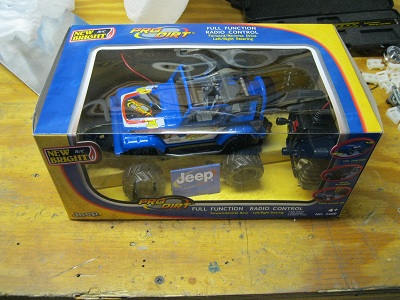
1.) First remove the RC car from the box (can be exciting) and verify it functions correctly.
out of the box

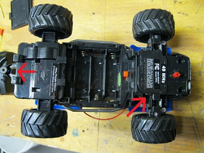
2.) Next remove the two screws marked by the red arrows to remove the top of the RC car
top off

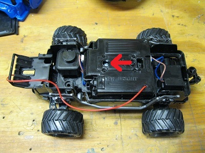
3.) Flip it over and remove the one screw marked. Once that screw is removed there are 2 clips you need to unlatch to remove the cover over the PCB.
pcb cover

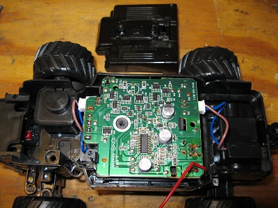
4.) Next there are 2 clips holding the PCB down to the body. Carefully unclip them and slowly lift the PCB up. You will need to compress one of the battery terminals to get it to pass though the batter compartment. Also the motor leads are plugged into the PCB there is a small latch on the bottom side of each that you need to squeeze in to release them. Note if your careful with the soldering iron you should be able to leave the PCB in the RC car and avoid a lot of work.
PCB out

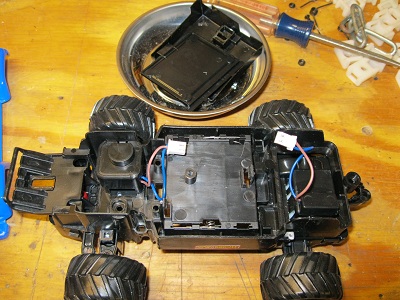
5.) And now the PCB is out. If i was not cost limited at this point I would have simplified the design by just running the two motor leads out the tether cable and putting a pair of double pole double throw on-off-on momentary switches in the control box along with a battery holder. Greatly simplifies the design but would have added another $10 -$15 for the switches and $5 - $10 for a battery holder.
raw mech base

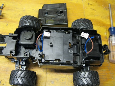
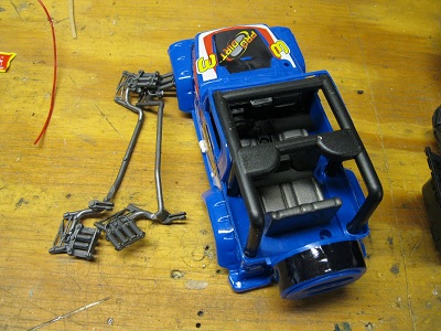
6.) At this point these parts can be tossed (unless you want to put them back on for looks)
Junk

7.) And these parts you want to make sure you keep. (battery cover and PCB cover are in the background.)
Keepers

8.) These cheap RC cars cannot easily be switched between frequencies so the RC transmitter and receiver are about worthless for competition. So we are going to convert this from a RC car to a wired car. Now a little bit of electrial theory. These cheap RC cars have a pair of simple H bridges driving the front steering motor and the rear drive motor. The circuit diagram looks a little like this for one motor.
circuit
To get the motor to run forward the forward input is pulled high (V+) so Q4, Q5, and Q1 turn on. This causes the upper motor terminal to be grounded and the lower one to be at V+ running the motor in the forward direction. In the case of reverse the reverse input is pulled high (V+) which turn on transistors Q3, Q6, and Q2. This causes the top motor terminal to be at V+ while the lower one is grounded. This causes the motor to run in reverse. Note both input CANNOT be high at the same time. If they were this would short V+ to ground through the transistors.
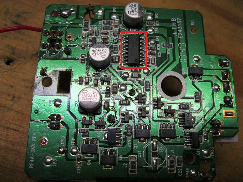
Normaly the forward and reverse inputs go to the RC reciever chip. So to make this cable controlled we are going to remove that controller chip (red box).
remove chip
Click to enlarge

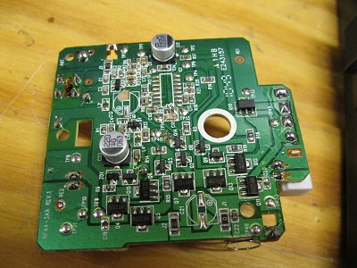
9.) Here is a picture of the board with the chip removed.
chip removed

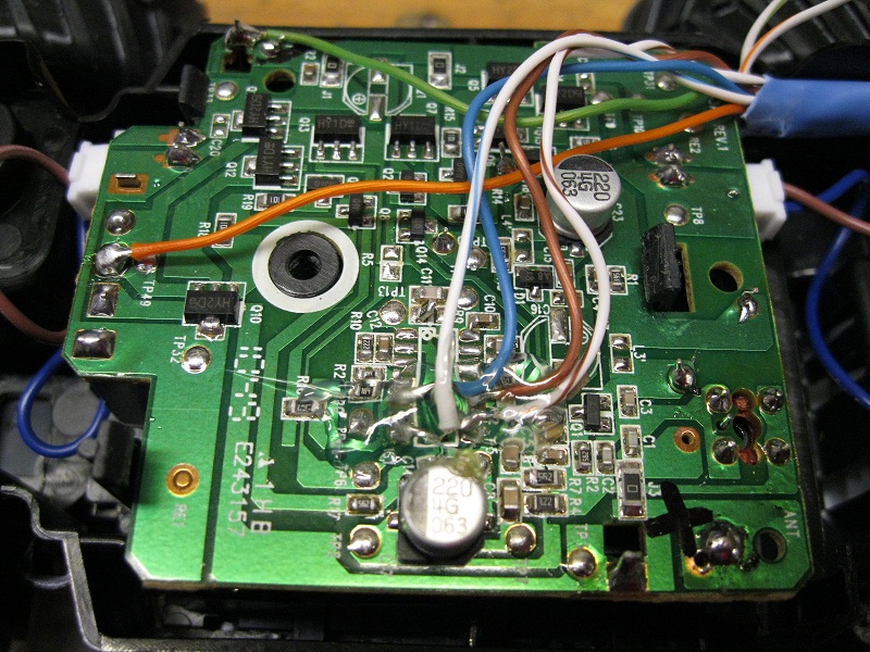
10.) Next add wires to V+, Ground, Forward, Reverse, Left, and Right inputs. Secure with hot glue to prevent the wires from ripping the traces off once you have tested all the inputs work. To reassemble the truck just revers the steps used earlier to take it apart. Note again if I had more to spend I would also add pull down resistors to keep the inputs from floating. But in my testing I did not see any false triggers so things look to be stable when floating.
Wires on
Click to enlarge

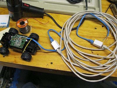
11.) Here is a photo of the test rig I used to verify everything was working before adding the hot glue. Touching the solid orange wire to any of the other input wires should trigger that input.
Test rig

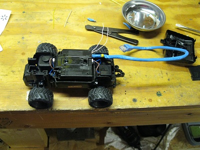
12.) First cut a slot for the cable in the PCB cover then reinstall the PCB cover and retaining screw. Drill 2 small holes in the side of the RC car and secure the cable to them using a zip tie. (see yellow item in photo above and bellow) Note the 2 extra wires sticking out of the cable. These are unused in this design and could be used to activate a second motor to run a ball scoop or claw.
pcb cover on

13.) At this point it it time to work on the controller. Since I am cash strapped I am just going to reuse the controller that came with the RC car.
controller

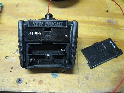
14.) Flip it over and remove the battery compartment door and screw. Once that is done you will need to unclip the 4 clips around the edge of the controller to get it open.
Controller back

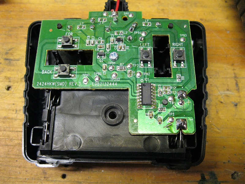
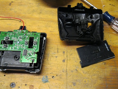
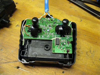
15.) Once open carefully set aside the controll sticks and it should look something like this.
pcb controllerparts and sticks
click to enlarge

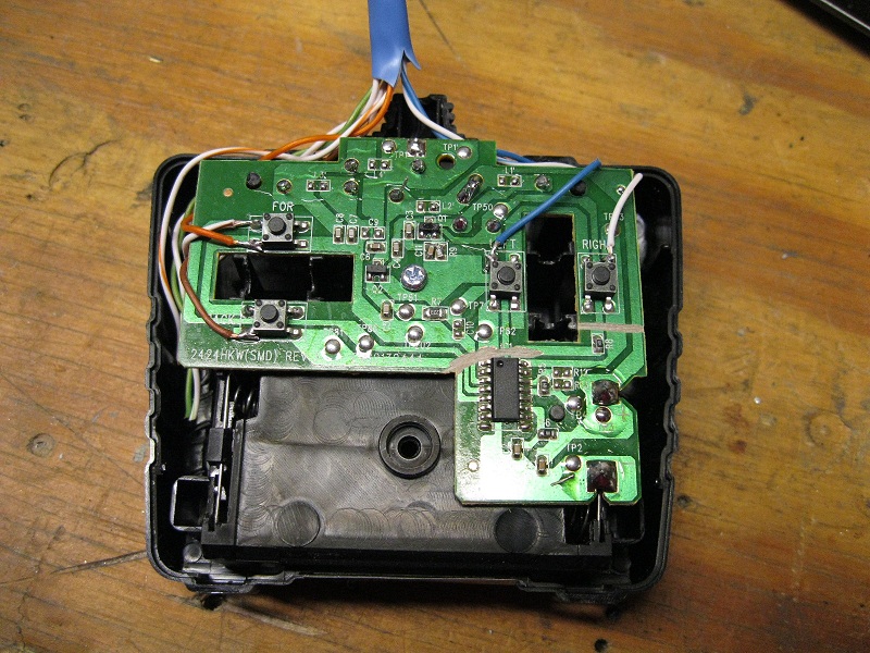
16.) Note the control chip in the lower left corner. Again that needs to be disconnected. They easist way in this case is to use a dremal tool with a fiberglass cutoff wheel to slice though the copper traces running down into that corner. Once that is done you just need to solder the wires in the RJ45 cable onto the switch legs. Note 2 legs on all four switches are connected together. This is where your orange V+ wire should go. The other four input wires should connect to one of the other 2 legs of their respective switches. Note the color code used on the RC car end will match the wire colors on this end. The remaing 3 wires (2 spares and ground) are not used and can be tucked under the PCB for later use.
controller wired
Click to enlarge

17.) Next replace the 2 joysticks
joysticks

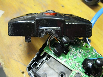
18.) At this point we need to modify the top cover to make enough space to pass the tether cable though. Easiest method is to cut some of the antenna boss off.
unmodified covermodified

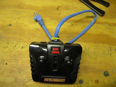
19.) Next snap the top cover back in place while taking care not to pinch any of the wires. Once in place replace the screw and battery door. This controler will NOT need to have any batteries in it. Just the 3 batteries in the lower unit are needed. Also zip tie the tether cable to the rear antenna boss.
finished controller

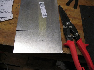
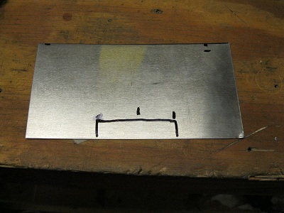
20.) At this point we have achived turning a cheap RC car into a even cheaper looking corded car. Now it is time to add a ball scoop. First cut off a 3" x 6" strip of aluminum. Note the tin sinips will leave a sharp edge. Its best to sand / file the edge after every cut to dull out this sharp edge. It is VERY easy to get nasty deep cuts on these edges. (paper cuts on steroids.)
cut a strip

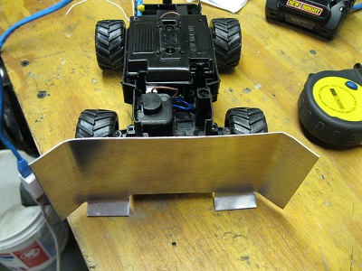
21.) This RC car happend to have 2 conveninet holes located on the front edge of the bumper. A 2" wide by 1/2" tab was about perfict to mount the scoop to these holes.
mounting tab

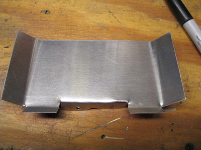
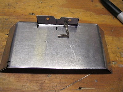
22.) Once that tab is cut and bent out you will need to tranfer the 2 hose and possibly add a notch to clear the steering adjusment. The easiest way to tranfer the holes is to use a mechanical pencil or a punch to mark the locations while holding the scoop in place. Once that is done drill the 2 holes and verify they line up. After that you can bend / cut the edges of the scoop to your preferance.
scoop 1Scoop 2

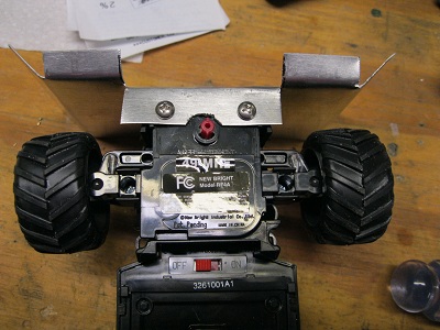
23.) Mount the scoop to the front bumper using two 6-32 screws (and nuts if needed. The holes in the plastic were slightly undersized so the screws held without nuts)
scoop mounted

And there you have it a VERY basic bot for Class 1 competition.
the bot

Now you might be thinking if that is all there is where is the fun? Like I said this is a VERY basic bot and has a lot of short comings. For instance it is very light and has little traction. There are lots of little tweaks like adding weight or coating the wheels that can either help or hurt its performance. Also there is more advanced improvements like replacing the flat scoop with a motorized grabber that can pick up the balls for transport vs just pushing them along.

And here is a quick you tube video of the bot running around my shop floor with some golf balls.