| News | |
| 10OCT09 | Project finished and web page created. |

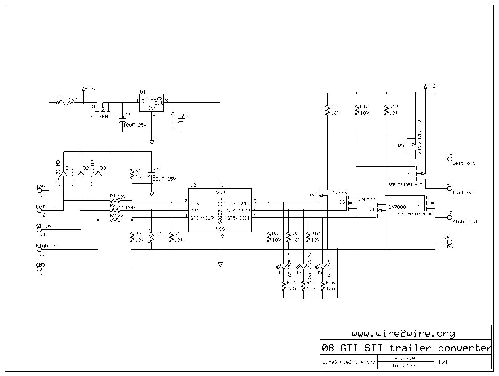
| Right click and chose "view image" to get a larger
version. Circuit explanation: - W1 - W5 are the inputs from the GTI. Note the ST terminal is not used in this case (added it in case I ever buy a car with ST lights) - D1-D3, R4, C2, Q1 Is a battery saver circuit. Running the micro draws about 5 to 10mA. If there are no tail signals for apx 1 minute C1 discharges and Q1 shuts off taking the current draw to 0. Startup on the micro is almost instant so there is no noticeable lag between the car and trailer lights on startup. - U1, C1, C3 are the 5V reg for the micro - R1-R3, R5-R6 make up the voltage shifter (~14V -> 5V) - U2 is the micro (where the magic happens) - R8-R10, Q2-Q4, R11-R13,Q5-Q7 Power driver output stage. Note Q5-Q7 will need heat sinks. - R14-R16, D4-D6 Status indicators (Left, Tail, Right) - W6-W9 Connections to trailer harness. As for mounting just about anything will do as long as Q5-Q7 are properly heat sinked. I embedded mine in a block of epoxy but a project box would have worked just as well. Download the full package (micro code, bill of material, logics, and PCB data) here GTI_STT_CONVERTER.zip. Also see the photo album for more details on how the circuit works and construction notes. |